September 2005
17
M9999-083005
MIC2588/MIC2594
Micrel
then add the rise in temperature due to the maximum power
dissipated during a transient overload caused by a short
circuit condtion. The equation to estimate the maximum
steady-state junction temperature is given by:
T
J
(steady-state) E T
C
(max) + 擳
J
(10)
T
C
(max) is the highest anticipated case temperaure, prior to
an overcurrent condition, at which the MOSFET will operate
and is estimated from the following equation based on the
highest ambient temperature of the system environment.
T
C
(max) = T
A
(max) + P
D
?(R
?J-A)
R
?J-C)
)
(11)
Lets assume a maximum ambient of 60癈. The power dis-
sipation of the MOSFET is determined by the current through
the MOSFET and the on-resistance (I
2
R), which we will esti-
mate at 17m& (specication given at T
J
= 125癈). Using our
example information and substituting into Equation 11,
T
C
(max) = 60癈 + [((3A)
2
? 17m&) ? (40 0.4)癈/W]
= 66.06癈
Substituting the variables into Equation 10, T
J
is determined
by:
T
J
(steady-state) E T
C
(max)+[R
ON
+(T
C
(max)T
C
)(0.005)
?(R
ON
)][I
2
?R
?J-A)
R
?J-C)
)]
E 66.06癈+[17m&+(66.06癈25癈)(0.005/癈)
?(17m&)][(3A)
2
?400.4)癈/W]
E 66.06癈 + 7.30癈
E 73.36癈
Since this is not a closed-form equation, getting a close ap-
poroximation may take one or two iterations. On the second
iteration, start with T
J
equal to the value calculated above.
Doing so in this example yields;
T
J
(steady-state) E 66.06癈+[17m&+(73.36癈25癈)?0.005/癈)
?17m&)][(3A)
2
?400.4)]癈/W
E 73.62癈
Another iteration shows that the result (73.63癈) is converg-
ing quickly, so well estimate the maximum T
J(steady-state)
at
74癈.
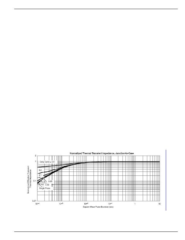
The use of the Transient Thermal Impedence Curves is
necessary to determine the increase in junction temperature
associated with a worst-case transient condition. From our
previous calculation of the maximum power dissipated during
a short circuit event for the MIC2588/MIC2594, we calculate
the transient junction temperature increase as:
T
J
(transient) = P
D
(short) ?R
?J-C)
?Multiplier
(12)
Assume the MOSFET has been on for a long time several
minutes or more and delivering the steady-state load current
of 3A to the load when the load is short circuited. The control-
ler will regulate the GATE output voltage to limit the current
to the programmed value of 4.2A for approximately 400祍
before immediately shutting off the output. For this situation
and almost all hot swap applications, this can be considered a
single pulse event as there is no signicant duty cycle. From
Figure 7, nd the point on the X-axis (
Square-Wave Pulse
Duration
) for 1ms, allowing for a healthy margin of the 400祍
t
FLT
, and read up the Y-axis scale to nd the intersection of
the Single Pulse curve. This point is the normalized transient
thermal impedence (Z
?J-C)
), and the effective transient thermal
impedence is the product of R
?J-C)
and the multiplier, 0.45
in this example. Solving Equation 12,
T
J
(transient) = (201.6W) ?(0.4癈/W) ?0.45 = 36.3癈
Finally, add this result to the maximum steady state junction
temperature calculated previously to determine the estimated
maximum transient junction temperature of the MOSFET:
T
J
(max.transient) = 74癈 + 36.3癈 = 110.3癈, which is safely
under the specied maximum junction temperature of 200癈
for the SUM110N10-09.
FIgure 7. Transient Thermal Impedance - SUM110N10-09
发布紧急采购,3分钟左右您将得到回复。
相关PDF资料
MIC2595R-2BM TR
IC CTRLR HOT SWAP NEG HV 14-SOIC
MIC280-7BM6 TR
IC SUPERVISOR THERMAL SOT23-6
MIC2800-GFSYML TR
IC REG TRPL BUCK/LINEAR 16MLF
MIC281-7BM6 TR
IC SUPERVISOR THERMAL SOT23-6
MIC2810-1JGMYML TR
IC REG TRPL BUCK/LINEAR 16MLF
MIC284-2BMM TR
IC SUPERVISOR THERM 2ZONE 8-MSOP
MIC3385-1.5YHL TR
IC REG DL BCK/LINEAR SYNC 14-MLF
MIC384-1YMM
IC SUPERVISR THERM LOC/REM 8MSOP
相关代理商/技术参数
MIC2594-2YM
功能描述:热插拔功率分布 Negative Voltage Hot-Swap Controller - Lead Free
RoHS:否 制造商:Texas Instruments 产品:Controllers & Switches 电流限制: 电源电压-最大:7 V 电源电压-最小:- 0.3 V 工作温度范围: 功率耗散: 安装风格:SMD/SMT 封装 / 箱体:MSOP-8 封装:Tube
MIC2594-2YM TR
功能描述:热插拔功率分布 Negative Voltage Hot-Swap Controller - Lead Free
RoHS:否 制造商:Texas Instruments 产品:Controllers & Switches 电流限制: 电源电压-最大:7 V 电源电压-最小:- 0.3 V 工作温度范围: 功率耗散: 安装风格:SMD/SMT 封装 / 箱体:MSOP-8 封装:Tube
MIC2594-2YM-TR
功能描述:Hot Swap Controller 1 Channel -48V 8-SOIC 制造商:microchip technology 系列:- 包装:剪切带(CT) 零件状态:停产 类型:热交换控制器 通道数:1 内部开关:无 应用:-48V 特性:故障超时,闭锁故障 可编程特性:限流,压摆率,UVLO 电压 - 电源:-80 V ~ -19 V 电流 - 输出(最大值):- 工作温度:-40°C ~ 85°C 电流 - 电源:3mA 安装类型:表面贴装 封装/外壳:8-SOIC(0.154",3.90mm 宽) 供应商器件封装:8-SOIC 功能引脚:DRAIN,OFF,ON,/PWRGD 标准包装:1
MIC2595-1BM
功能描述:IC CTRLR HOT SWAP NEG HV 14-SOIC RoHS:否 类别:集成电路 (IC) >> PMIC - 热交换 系列:- 产品培训模块:Obsolescence Mitigation Program 标准包装:100 系列:- 类型:热插拔开关 应用:通用 内部开关:是 电流限制:可调 电源电压:9 V ~ 13.2 V 工作温度:-40°C ~ 150°C 安装类型:表面贴装 封装/外壳:10-WFDFN 裸露焊盘 供应商设备封装:10-TDFN-EP(3x3) 包装:管件
MIC2595-1BM TR
功能描述:IC CTRLR HOT SWAP NEG HV 14-SOIC RoHS:否 类别:集成电路 (IC) >> PMIC - 热交换 系列:- 产品培训模块:Obsolescence Mitigation Program 标准包装:100 系列:- 类型:热插拔开关 应用:通用 内部开关:是 电流限制:可调 电源电压:9 V ~ 13.2 V 工作温度:-40°C ~ 150°C 安装类型:表面贴装 封装/外壳:10-WFDFN 裸露焊盘 供应商设备封装:10-TDFN-EP(3x3) 包装:管件
MIC2595-1YM
功能描述:热插拔功率分布 Negative Voltage Hot-Swap Controller - Lead Free
RoHS:否 制造商:Texas Instruments 产品:Controllers & Switches 电流限制: 电源电压-最大:7 V 电源电压-最小:- 0.3 V 工作温度范围: 功率耗散: 安装风格:SMD/SMT 封装 / 箱体:MSOP-8 封装:Tube
MIC2595-1YM TR
功能描述:热插拔功率分布 Negative Voltage Hot-Swap Controller - Lead Free
RoHS:否 制造商:Texas Instruments 产品:Controllers & Switches 电流限制: 电源电压-最大:7 V 电源电压-最小:- 0.3 V 工作温度范围: 功率耗散: 安装风格:SMD/SMT 封装 / 箱体:MSOP-8 封装:Tube
MIC2595-1YM-TR
功能描述:Hot Swap Controller, Sequencer 1 Channel -48V 14-SOIC 制造商:microchip technology 系列:- 包装:剪切带(CT) 零件状态:停产 类型:热交换控制器,序列发生器 通道数:1 内部开关:无 应用:-48V 特性:闭锁故障 可编程特性:限流,故障超时,UVLO 电压 - 电源:-80 V ~ -19 V 电流 - 输出(最大值):- 工作温度:-40°C ~ 85°C 电流 - 电源:4mA 安装类型:表面贴装 封装/外壳:14-SOIC(0.154",3.90mm 宽) 供应商器件封装:14-SOIC 功能引脚:CFILTER,CNLD,DRAIN,PGTIMER,OFF,ON,PWRGD1,PWRGD2,PWRGD3 标准包装:1
